Data Center Environment and Power Equipment Monitoring: The Key Role of PDU Power Integration
The Watchdog IT operations monitoring system focuses on monitoring core technologies such as servers and network equipment, while also emphasizing the monitoring of the data center environment and power equipment to ensure efficient and reliable overall system operation.
Through auxiliary monitoring functions, we not only improve operational efficiency but also ensure the stability and safety of the data center.
Role and Contribution of Auxiliary Monitoring:
➢ Integrate the operational status of various equipment in the data center to ensure smooth data flow.
➢ Connect different equipment and systems to enhance the collaboration efficiency of the data center.
➢ Provide third-party monitoring data for performance evaluation.
➢ Become part of a comprehensive maintenance solution to improve overall system stability.
➢ Standardize the alarm handling process to promptly address potential issues and prevent risks.
Core Value of PDU Power Equipment Monitoring:
Through comprehensive monitoring, we strive to prevent any power issues that may affect system stability, thereby enhancing system operational efficiency and reliability.
Detailed Specifications of PDU Power Equipment Monitoring:
➢ Detection Target: Monitor PDU power usage to avoid overload and statistics on power consumption. Dual monitoring increases system safety.
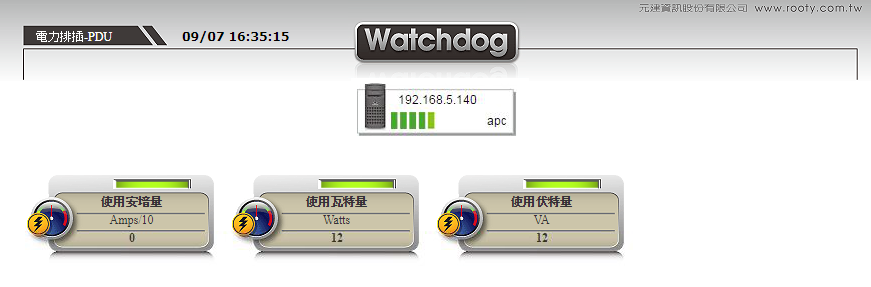
➢ Monitoring Indicators: Include amperage (Amps), wattage (Watts), and voltage (VA) to comprehensively control power usage.
➢ Alarm Settings: Set alarm conditions based on minimum or maximum data to prevent anomalies.
➢ Real-time Updates: Provide real-time data and alarms to ensure immediate updates.
➢ Information Aggregation: Integrate the release/cancellation time of information, data, and alarms for subsequent analysis.
➢ Emergency Response: Immediately notify and execute emergency procedures when an anomaly is detected to ensure a quick response.
➢ Alarm Thresholds: Clearly define alarm values for precise monitoring.
The alarm thresholds for the PDU power equipment monitoring items are as follows:
➢ Handling strategy when data cannot be obtained.
➢ Define the minimum and maximum thresholds for amperage (Amps) to prevent extreme situations.
Comprehensive Control of PDU Power Usage:
The application of the IT operations monitoring system in the data center operations is not limited to the monitoring of servers and network switches, but also includes comprehensive detection of the data center's surrounding environment.
Especially the application of the PDU power strip function, through the calculation and monitoring of the total current (amperage) of the PDU power strip,
calculate the total power consumption of the data center to avoid the risk of accidental power outages.
By setting the maximum and minimum total current alarm values for the PDU power strip, you can precisely control and monitor power usage to ensure the stability and safety of the data center environment.
In addition, by counting the total wattage and total voltage, maintenance personnel can understand the power usage of the PDU, enhancing the control and management of the data center's operational status.
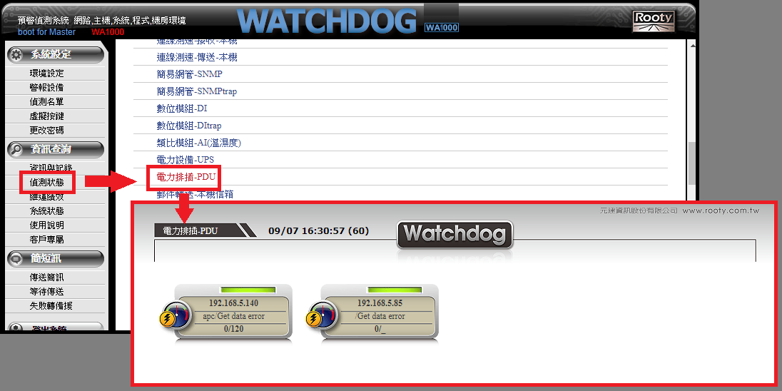
The Watchdog IT operations monitoring system provides both graphical and textual monitoring functions, allowing maintenance personnel to effectively and quickly grasp the operating status of the PDU power strip in the data center.
Introduction to Graphical and Textual Monitoring:
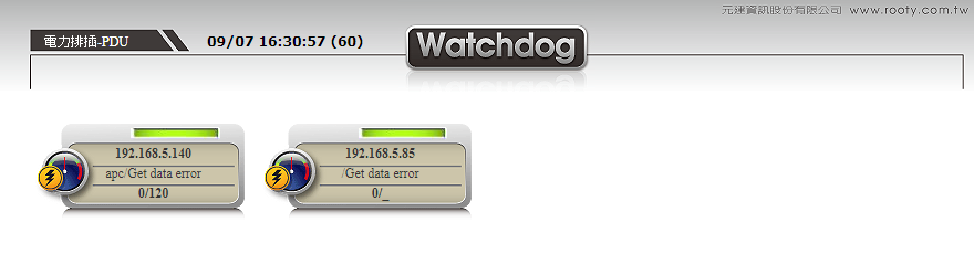
1. Graphical Monitoring: By clicking on the detection points in the large PDU power strip detection map, maintenance personnel can enter a more detailed detection screen.
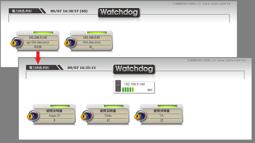
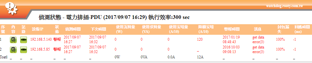
2. Textual Monitoring: Textual monitoring provides real-time updates on data such as wattage (W), voltage (VA), amperage (A/10),
including rich monitoring information such as content, records, device IP, status, detection time,
next detection time, de-rating amperage (A/10), alarm time, messages, packet loss, and response time (ms).
Performance Analysis Application:
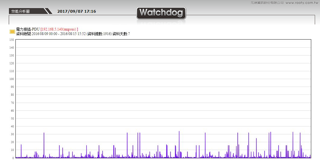
1. Weekly Performance Analysis: By setting the start date of the week, maintenance personnel can easily observe the usage dynamics of the detection target in the short term.
This is the most appropriate chart to observe the short-term data information fluctuations.
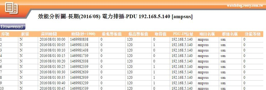
2. Long-term Performance Analysis: In the long-term performance analysis, you can mainly adjust the month of data analysis to obtain the long-term analysis data for that month.
This includes information such as serial number, status, data time, time, minimum alarm value, maximum alarm value, obtained value, PDU IP address, item name,
group name, and performance level, which helps maintenance personnel conduct in-depth long-term trend analysis.
When setting up PDU monitoring, ensuring that your PDU device supports SNMP functionality is the primary condition.
Below is a rough introduction to the settings:
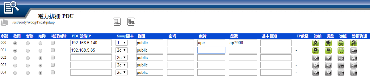
Basic Setting Items:
➢ Basic information settings of the PDU device, including device IP, SNMP version, model, brand, and basic alarm conditions.
➢ Specific version selection of SNMP, supporting versions 1, 2C, and 3.
➢ Set the group name and password to meet the security requirements of network management.
➢ Selection of brand and model, supporting multiple brands including USHA, APC, THER, etc.
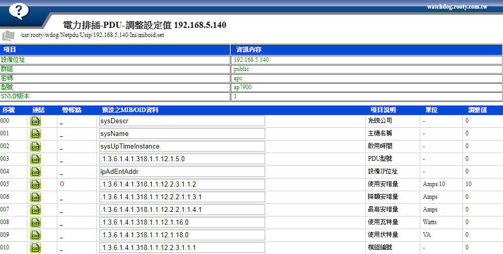
Default and Fine-tuning of MIB/OID Table:
➢ Initial settings automatically provide corresponding SNMP MIB/OID tables based on the selected brand, including port usage and quantity.
➢ Provide fine-tuning functions, allowing maintenance personnel to adjust MIB/OID settings according to needs, including testing single MIB/OID data capture.
➢ Setting alarm thresholds, allowing specific MIB/OID to set alarm conditions so that maintenance personnel are immediately notified when data exceeds the normal range.
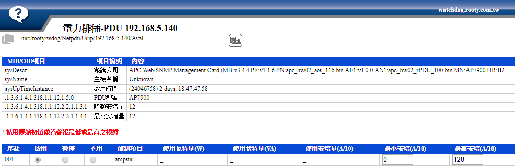
Notes
➢ If using amperage (Amps), alarm thresholds can be set, defaulting to the maximum amperage of this PDU
➢ Usage wattage (watts) and voltage (VA) are only for data collection for analysis and statistics, and cannot set alarm thresholds
➢ If the minimum and maximum alarm thresholds are set to 【0】, alarm values will not be detected
➢ An alarm message will be issued if the data cannot be obtained
➢ The alarm thresholds and obtained data for amperage (Amps) are in units of 1/10 amp (100mA)
The above is a rough overview of the settings. For detailed operation procedures, please contact Root Information-Watchdog professionals.